Table of Contents
Lab Notes for the Scanning Tunneling Microscope
These are the lab notes for the STM. See the STM Project Page for an overview of the project.
This page is a lab notebook. It documents the work done in the lab and our thoughts, theories, and findings related to it. Everything you read here is work in progress and not final results. We believe it is best to have our lab notes out in the open, because it gives more detailed insight into what worked for us and what didn't. Of course you can also use this page to follow our progress!
Day 2026-01-11 (k8ik, rahix)
Currently, work is focused on setting up a precise interferometer which we can use to characterize movement of the STM stage.
Progress is documented here: Lab Notes for Optics Experiments
Day 2025-09-20 (rahix)
Modelled more of the as-built of the current STM setup in mechanical CAD so we have a reference model:

Day 2025-09-07 (rahix)
Took the video capture from yesterday, of the beam bouncing from the STM off a mirror 2.35m away and back to the camera on the STM and ran some analysis on the data.
Analysis works like this: For each frame, we find the beam center. Then we look at the spectral content of the displacement in X and Y directions. Check the full notebook for details: Laser-Wobble.ipynb from Calculations/ (Rendered Notebook).
Here is the final figure:

The most interesting result is the peak highlighted by the red line. The red line marks the theoretical resonance frequency of the vibration isolation system that we had calculated in the past. Seeing a peak right at this frequency sparks a lot of confidence!
The results are limited up the 15 Hz because of the 30 fps video capture. But towards the right of the figure, the data becomes pretty meaningless anyway as the displacements are too small for the camera to pick up already.
Day 2025-09-06 (rahix, q3k, hugo)
Rebuilt the entire experiment to clean up the space and install some shelving. All connections are remade but the setup has not been reverified to tunneling.
Set up the laser again to make some more measurements of the beam. The following pictures show the beam at different distances. Left to right: 50mm, 100mm, 200mm, 400mm. The 400mm measurement includes a mirror which is why the orientation is flipped.


The size change derived from the FWHM in these pictures would be about 0.6mrad, but this is most likely not at all a dependable result.
Set up the laser to bounce off a mirror 2.35m away and back onto the STM vibration isolated mount. Installed a ø2mm aperture in front of the beam to slightly tighten the profile. This way we can watch the beam jump around on the camera. Recorded 8 minutes of footage in hopes that we can recover the low-frequency content of the vibration isolation transmittance from this.
Turned on the STM again and managed to get (very very unstable) tunneling. So everything was set up correctly again! The tip is still the broken one from the failed runs last time. Adjusted the sample holding to avoid the collision that happened back then. The STM is currently not covered in aluminum.
We noticed that the vibration isolation is bouncing around a lot more after the rebuild. It seems this is caused by it now standing on a different part of the table that is not rigidly fastened to the table frame. We should put some effort into stiffening the table structure here.
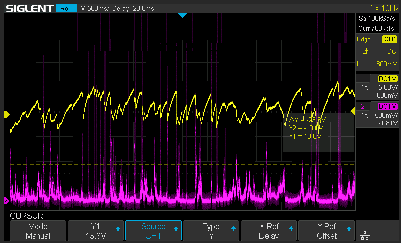
Here is an overview of the current status of the experiment after it was rebuilt:

- Oscilloscope
- Yellow: Z displacement (control variable, this is the “output” signal)
- Pink: Tunneling current scaled to 0-5V
- Blue: X displacement output
- Green: X displacement input
- Multimeter (set to DC voltage
- Setpoint current (
Sollstrom) in 1V/nA (so 0.100V is 100pA)
- Laptop
- Connect white USB cable from the Raspberry Pi Pico
- Temperature Measurement using
serial-monitor-rustas detailed on 2025-08-23
- Red Pitaya (not currently running)
- Can also measure the Z displacement (
IN1) - And output the X displacement (
OUT1)
Day 2025-09-05 (rahix)
Set up the beam camera for a test whether this whole plan of using the camera for interferometry will work. Pointed the bare cheapo laser diode at it.

Configuring the camera is very odd — it seems you cannot directly set the exposure. It seems that triggering the auto white balance once auto-fixes an adequate exposure. Got to take a somewhat decent shot after then resetting all three white balance color channels to 50.

Analyzing this image for beam quality, using Laserbeam.ipynb from https://git.fa-fo.de/fafo/k8ik-stm/src/branch/main/Calculations.

Please keep in mind that the sensor size is not precisely known as of right now so the absolute measurements in the image above are probably off by up to 20%.
Day 2025-08-28 (rahix)
Performed a study of the dimensions involved in our system based on some yet-to-be-confirmed assumptions. This gives us some nice potential explanations for the behavior and lots of leads for probing the correctness of this model. Keep in mind that all the results detailed below hinge on the assumptions detailed here.
Assumptions
- Our piezo actuators have a maximum deflection of 0.3±0.1µm for the maximum voltage of +10V that we apply. This was derived from looking at a similar piezo actuator's characteristics (KEMET AE0203D04DF).
- Our piezo actuators deflect by 31±10nm/V with a linear response between 0 and +10V. We do not make assumptions about the behavior with negative bias as this is not characterized for the reference actuator either (they actually explicitly do not recommend negative bias).
- Under the observed stable temperature conditions (drift by -0.04°C/min) we assume a worst-case thermal expansion of 18nm/min. Real expansion is most likely below that as expansion of the different components will largely cancel out.
- Tunneling currents require a distance of tip-to-sample below 1nm.
Derivations
Combining these assumptions with previous measurements lets us make some claims:
- The DVD sample we are looking at has a track spacing of 0.74±0.03µm (see ISO/IEC 16448:2002). We will not be able to resolve two tracks in one picture with the deflections of the piezos that we can achieve. We may or may not be able to resolve a single pit which is about 320nm wide.
- The measured control response from
2025-08-27with a peak-to-peak amplitude of 2.2V corresponds to a distance variation of 90±22nm. During these variations, the control system is able to keep the tip in range regardless. - In these 90±22nm variations, the change from adjusting tunneling current setpoint is vanishingly small. This matches an expected change of a few Å (0.1nm) which correspond to a control signal change of 3±2mV. Even a 1nm change would not be discernible at all.
- Worst-case temperature drift would show up as a steady slope of 0.65±0.21V/min. We are not seeing that so thermal expansion must have a much lower effect.
Day 2025-08-27 (mina, zdmx, rahix)
Tried setting everything up again. The temperature sensor seems “stuck” at always reporting 25°C. After a bit of investigation, it turns out that today it's too cold for the setup to work! We accidentally designed the setup such that we can measure only down to exactly 25°C:
- The ADC can only measure ±0.5×Vdd
- At 25°C, the 10k resistor and the 10k NTC thermistor divide to exactly 0.5×Vdd
- Below 25°C, the voltage rises above this limit
To fix this, we replaced the 10k resistor with a 15k resistor. Now we can measure down to 16.2°C!
During debugging, we uncovered the STM from its aluminum foil cover. Recovered it after the sensor was fixed.
Tried to achieve tunneling again, but it's very sensitive today and only extremely short runs without stable control are possible. Assuming the tip has gone bad from the earlier interference with the system.
Opened up the STM again and replaced the tip with a new one. After installation of the tip, when doing the coarse-coarse approach with the front two micrometer screws, we noticed a lot of spontaneous noise on the tunneling current signal. We found that the noise can be increased by touching the insulation of the short coax run to the preamplifier. Assuming this is to be expected and nothing new.
Reinstalled the aluminum foil. Touching the aluminum foil also produces visible noise in the tunneling current. Maybe it is static charge from the floor today?
Very very sensitive tunneling after the first approach.
Heated up the STM again (peak change was 0.7°C) and then let the temperature settle to a very stable value. After lots of fiddling, achieved another tunneling run for ~3 minutes where we could vary the current setpoint again (0-800nA).
After this one, achieved another tunneling run of ~5:20 minutes with the ability to vary setpoint. Left setpoint at 546pA. Control response for the Z axis has a peak-to-peak deviation of about 3V but does not change abruptly.
Heated up the STM until it changed by a whole 1°C. Let it cool until it stablilized to a constant decrease of -0.006°C/min. We then achieved a tunneling session of over 20 minutes. Took some pictures of the oscilloscope screen during the time and noticed some interesting facts:
- The control response to random pertubations is indeed much larger than the response to setpoint current changes. We cannot even make out the response to setpoint changes reliably.
- The control response is on the order of 1kHz and had a peak-to-peak amplitude of about 2.2V.
- There are a lot of short “collisions” (<1ms) where the current rises to preamplifier saturation.


At some point it stopped again. We were not able to reproduce another stable tunneling sequence again.
During the attempts, we noticed a very high hysteresis in the micrometer screw movements which makes adjustment extremely difficult.
Noticed a very strange and worrying phenomenon: When driving the tip down further and further using the back micrometer screw, first we get contact, then contact is lost again, then we get contact again, it stops again. etc. Thhis happens over many rotations of the screw (many 10 µm) but not always in the same angular positions of the screw (sometimes it happens aready after half or e.g. 1/8th of a screw rotation).
Opened the alu foil again to check what's up. Well… turns out the terminal where the tip is mounted is now sitting on the small copper piece clamping down the sample. Ugh, that explains a lot!

We did not have time to fix it today. Next time, need to a) adjust sample mounting to avoid this collision b) check for a large hole in the sample c) replace the tip once again.
Day 2025-08-24 (rahix, hugo)
Re-setup the temperature monitoring. Today we are seeing a constant increase in temperature with a drift rate of approx. +0.001895 °C/min. The lid is on and had not been removed since yesterday. The temperature probe is still stuck to the lever arm of the STM.
Encountered some more glitches in the temperature readout, leading to the monitor firmware crashing. Added workarounds.
Running a long temperature measurement to understand influences.
- Opened window at 2070s into the measurement.
- Window was closed again at 3500s.

(There were two ADC readout glitches that we haven't yet investigated further…)
It is interesting to see how slow the temperature inside the STM was to respond after the window was closed again.
Started rebuilding the STM experimental setup. Everything should now be as it last was.
The multimeter for the setpoint current Sollstrom is always showing 0.0V right now. Ah, the alligator clip was clipped to the wrong lead of the poti for some unknown reason. It needs to be on the black wire. Now we can visualize the setpoint again.
Played a bit with the open-to-air STM, managed to achieve somewhat stable tunneling (a few 10 seconds to a minute) a few times. The tip is still the old one. Played with the Sollstrom from 200pA to 60pA. Drift is generally still observable.
Quite a bit of experimentation followed (explanation of the graph details below):

Then started wrapping the STM head in aluminum foil to stabilize temperature. The effect is quite well visible in the graph below.
Because we could not achieve much tunneling anymore after the first installation of the aluminum foil, removed it again and replaced the tip. Then reinstalled the foil after installig the new tip. Retried tunneling with mixed results.
The PI controller is still correcting the tip down towards the sample which means the sample is drifting “away” from the tip. In parallel, the temperature graph above shows a constant increase at roughly 0.010 °C/min.
During the flat period on the temperature graph, a long time stable tunneling streak was possible. But it is unclear whether it is has anything to do with the temperature behavior…
Heated up the STM with its aluminum foil isolation from the outside. Temperature response is quickly visible.
After the temperature settled again, there was another longer period of tunneling possible. During this period, we also changed the current setpoint from 80pA to 210pA. After some time it drifted out of range again.
Heated up the STM again, a bit more this time. Unexpectedly, during heating, the STM started tunneling on its own for a while. Then it fell into sample contact. Does this suggest that the expansion of the STM makes the tip move closer to the sample rather than away? At least this observation sort of puts the temperature response into perspective: It is very unlikely that the smaller temperature drifts from earlier have any direct effect.
During the cooldown of the STM, a very interesting “tunneling” situation was achieved: The control signal is very noisy, but at the same time the PI controller found its operating point on its own again and again. The current signal looks very noisy as well, though. This might also be a very weird noise situation instead of real tunneling? At some point it stopped and the current signals also stopped being noisy.
Let the temperature settle again (no longer visible in the graph above).
—
One effect that is still worrying and unexplained is the sudden sharp jumps that are often seen in the control signal (e.g. see this older capture: 2025-06-15_20-50.png). They always correspond to noise spikes in the current signal, but most likely are not actually signal. Why does the current signal spike like this? Should this be filtered before going into the PI controller? I also assume the fast piezo movements resulting from this are having a very negative impact on stability.
Achieved one more very long tunneling session with some interesting observations:
- Noisy current signal, but none of the spikes → the control signal also has no jumps in it and just steadily follows the current.
- We can freely vary the setpoint current up to above 1nA (!) and the measured current follows this which means the system is in control.
- But even over these large variations, almost no discernible change in the relative value of the control signal is visible. Is it so sensitive that we cannot even see the offset change?
- But still, there are large variations in the control signal. It would be interesting to know what would happen if those had been filtered out?
In summary:
- There probably is a temperature response, but the scale is much higher than the background temperature drift we observed yesterday.
- Isolating the STM with aluminum foil does have a very noticable stabilizing effect on the temperature changes. Assuming that the main effect here is shielding from ambient air movement.
As a next step we should attempt to recreate the stable tunneling situations that were achieved today. Then we can retry running some X-axis scans with the Red Pitaya.
Day 2025-08-23 (rahix, q3k, rob, hugo)
Started building a temperature monitor for the STM, based on a very cheap CS1237 ADC breakout board and a 10k NTC thermistor (MF52B 3950K). Found a blog post documenting the ADC and a MicroPython driver for it.
Wrote a small script for readout, which can be found here: https://git.fa-fo.de/fafo/k8ik-stm/src/branch/main/Misc/Temp-Monitor
The script outputs roughly correctly scaled temperature values. The absolute values are probably completely bogus but relative changes are a reliable signal.
Using the very nice serial-monitor-rust tool to plot the values coming in live. Unfortunately, there are some glitches in the serial data, making this display somewhat less useful. The glitches seem to appear in the serial data stream, they look like repeated characters. Odd, because this is a USB-serial directly from the rp pico to the host…
For the moment, it's easiest to use my fork of theserial-monitor-rust. Install it using this command:
cargo install --git https://github.com/rahix/serial-monitor-rust
And then run it using this command to automatically set everything up correctly for display (you may have to select a different serial device, of course):
serial-monitor-rust --column 'Raw' --color '808080' --column 'Temperature' --color '0080ff' /dev/ttyACM0
Put the sensor inside one of the aluminum extrusions of the STM frame (the inner circular channel) to thermally connect it to the frame somewhat. Ran a measurement over ~10min to see what we can measure (the following data was cleaned from the serial glitches):

We are seeing the frame cool down by 0.446°C over the 11 minute measurement. This equates to a temperature drift of -0.0394°C/min (uncertainty not considered here…).
Doing a ballpark calculation of thermal expansion: Assuming 20mm of aluminum (⍺ = 23 µm/m°C), this is a drift of 18nm/min. Don't trust this value too much at this point.
Slowed down the serial reports to once every 200ms to hopefully stop the serial glitches from occuring. Seems to have worked well! Here is another run of ~16 minutes:

This time, got a drift of -0.01756°C/min. Assuming it slowed down as it is getting closer to ambient or so. To note, the window in the storage room was open during these measurements, leading to some air exchange with the colder outside air of the night. Windows in the main room were closed and only one person was present.
So far, it is unclear whether this drift actually relates to the drift of the STM. This should be investigated in a next step. For this, we need to find a way to couple the temperature sensor to the STM, as close to the probe as possible.
Mounted the thermistor onto the STM, on the lever arm that's holding the XYZ piezo stage. For now, it is just held down by a piece of tape with no further efforts to thermally couple it to the aluminum part it is sitting on. This might mean the response curve is not quite following the temperature of the aluminum as fast as it could. Let's see.
A note on the general performance of the temperature monitor: We are easily resolving changes below 0.01°C, very good.
In the new location on the STM, the temperature measurement is quite a bit more noisy. Unsure how much of this needs to be attributed to bad thermal coupling. Here's a graph anyway:

Day 2025-08-02 (k8ik, q3k, rahix)
Tried imaging the DVD surface under the SEM for reference. Had a bit of trouble getting an image to become visible → turns out that the surface is only visible at low acceleration voltages and becomes very invisible the higher it gets. Finally worked well at 5kV and using SE imaging mode.
The samples were prepared by lifting the bottom plastic off the DVD such that the aluminum foil sticks to the remaining plastic which also has the label printed on its back. So we are looking at the sample from the same side as the DVD drive laser.

(The dimensions are off, because of our SEM not being calibrated properly)
Track to track pitch on a DVD is 740nm.
We now know that our samples are good and we should be able to image them on the STM! Also found some prior art of imaging DVD surfaces with an STM, further corroborating that this approach will work:
Day 2025-07-12 (k8ik, rahix)
Rebuilt the experiment to the last state (oscillscope for live viewing, red pitaya for acquisition and x/y control, lab power supply).
Made a new tip to reproduce tunneling. Experimented a bit with different tip cutting strategies to see whether we can improve our results with better tips:
- Tried cutting a tip flat, without pulling
- Seeing very weird offset currents when getting somewhat close to the sample. These are definitely not tunneling effects.
- The offset seems to throw off the PI controller quite a bit
- Not able to achieve much stable tunneling
- Tried cutting a tip at an angle, but with much less pulling force
- Very very good results, achieving tunneling got considerably easier
- Almost no hysteresis around the probe touching distance, making coarse approach very easy
- Hypothesis: The tip is now much more stubby which makes it less prone to bending during sample contact.
Also started to put more effort into making sure the tips are inserted straight into the STM.
Made the C7 capacitor hack more permanent by soldering the capacitor to the respective terminals rather than wiring it in with alligator cables.
New address for the Red Pitaya Notebook: http://redpitaya.lab.fa-fo.de/jlab/lab/tree/RedPitaya/Fafo/STM_Control.ipynb
Wrote a new script for sweeping one of the red pitaya: http://redpitaya.lab.fa-fo.de/jlab/lab/tree/RedPitaya/Fafo/STM_Sweep.ipynb
Connected the output of the Red Pitaya (CH1) to the X input of the control box.
Added a 1k resistor parallel to R17 to increase the X-axis gain from 1 to 11. This means the input voltage is now -1V to 1V rather than -10V to 10V.
Managed to take some sweep recordings while the STM was tunneling:


We definitely can't see any surface here, but we could reliably observe that the X movement slowly moved a stable tunneling out of range.
Day 2025-06-29 (rahix, k8ik, q3k)
Had troubles to get stable tunneling current, went to
Probenvorspannung: MaximumSollstrom: 0.144V (= 152pA)I: 5 (instead of 9 turns up (out of 10))P: 9 1/8 turns up (out of 10)
And now we get stable tunneling current for several minutes. We will for now continue with those settings.
Started integrating the Red Pitaya for X-Y scanning. As a first step, connected the Z-output of the control box to IN1. Added a BNC splitter so we can still see the control signal on the real oscilloscope. Once tuning the STM to tunneling range, we can now acquire the control-loop output from a Jupyter Notebook. Needed to update the firmware.

Access to the live notebook (only works from the lab): http://10.250.240.129/jlab/lab/tree/RedPitaya/Fafo/STM_Control.ipynb
A copy of the notebook is synchronized to git (please update!): https://git.fa-fo.de/fafo/k8ik-stm/src/branch/main/Control
New image of tunneling current after firmware update of the Red Pitaya and new script with the new Red Pitaya python API:

Right now the script is still very unusable, even for pure acquisition. We assume a problem is that the decimation factor is way too high at the moment. We should also look into what RP calls “Deep Memory Acquisition” to not be limited to the 16k sample buffer size.
Started making a bunch of new tips to see whether there is significant difference between them. There is, some tips are way easier to get to tunnel. ⇒ We need to work more on tip making skills to get reliable results here.
Day 2025-06-28 (k8ik, rahix, zdmx, guest)
Rebooted the experiment, electronics still work. The old tip doesn't work anymore, we are unable to achieve reliable tunneling.
Installed a new tip. Got controlled tunneling again from time to time, but not for long periods.
Made yet another tip. Now hysteresis of the micrometer screw is gone, but we still only tunnel for short periods before drifting away. Assuming temperature drift.
Installed a PT100 RTD on the sample holder of the STM to monitor temperature. The PT100 is connected to a 3.3V power supply and a resistor divider with 100R. Unfortunately, the RTD responds way too slow for any useful results. Aborted the experiment. We should get a different RTD to build a useful temperature monitor.
Day 2025-06-15 (rahix)
Tried reproducing the results from yesterday → achieving tunneling was quickly done. The goal today is to tune the control loop better.
Achieved control for short periods of time, but the control behavior looks way too slow:

Assuming that the proportional control is not doing its job right now.
Added back an R8 of 100k to shut up the I-controller, to just look at the P-controller. It shows its familiar ringing when giving a factor using the potentiometer. This even couples back into the probe current, as can be seen below (at this time, the tip is very far away):

Frequency of the ringing is 1.47kHz.
Added another 1µF capacitor across C7. This gets rid of the ringing across the whole range of the P potentiometer.
With this, we are now able to see actual stable control over long periods of time with fast response from the control loop:


You can also see the piezo sweep using the I-controller until it finds the tunneling point.

What's still a bit unclear is how there can be situations like in the image above where tunneling stops again as the Z piezo moves even closer?
Part of a very stable tunneling over a very long period today:

During mechanical adjustment, the controller now sweeps until it finds something (left side of the picture below). On the right, it has gone into control.

Settings during the experiments above:
Probenvorspannung: MaximumSollstrom: 0.322V (= 322pA)I: MinimumP: Maximum
Now changing the settings somewhat in hopes of getting the control loop more tight:
Probenvorspannung: MaximumSollstrom: 0.144V (= 144pA)I: 9 turns up (out of 10)P: 9 1/8 turns up (out of 10)
You can see the faster I-response at least:

It seems the noise has increased since yesterday. We don't have values from before, but right now, seeing ~80mV of noise overlayed over the tunneling current signal.
After some time, the control loop settled down quite a bit, assumingly because process disturbances decreased for some unknown reason:


Managed to increase the setpoint current to 456pA:

Finally tried putting the lid onto the STM for noise shielding, but I think I crashed the tip way too hard during the process as I couldn't achieve stable tunneling again afterwards…
Should create a new tip next time and then retry more gently. Also X/Y control is probably a good next step.
Day 2025-06-14 (rahix, k8ik, hugo, q3k, ln, zoe)
Changed power supply from lab power supply to batteries to check source of 50Hz noise. Took four 9V block batteries to generate +18V/-18V and connected to power input on control unit. 50Hz noise on exact same level as with lab power supply. Current explanation: STM is still on ground of building which seems to be the source of the noise. STM is here grounded via the scope we use which is connected to ground. Currently checking whether it's possible to have it in floating ground mode.
When
- turned off, we measure 120mV with the multimeter (between exit of first amplification stage and ground)
- tunred on, we measure 2,8mV, ——“——
- turned on with connected ground we measure 5,5mV
Taking other scope makes no difference.
Adjusting the amplification steps with the rotary switch on the amplification board gives further questions:
- Highest amplification stage - to the very right (clockwise) - 10 MOhm - gives saturation of the 50Hz noise (rectangular, +/- 5V)
- Second amplification stage - second to the right (clockwise) - 1 MOhm - gives additional to 50Hz a 12kHz noise in saturation (+/- 5V)
- Third amplification stage - third to the right (clockwise) - 100 kOhm - gives 50Hz with 100mV amplitude with 12kHz in saturation (+/- 5V)
- Smallest amplification stage - to the very left (clockwise) - 10kOhm - gives a clear 50 Hz noise with 100mV amplitude
We now soldered in a very professional, Rahix-approved way, a 1 nF capacitor parallel to the second amplification stage into the amplifier board:
We got rid of the 12kHz!!
- 10MOhm: Saturated
- 1 MOhm: Saturated
- 100kOhm: 1V Amplitude
- 10kOhm: 100mV Amplitude
Without ground we measure ~250mV rms (completely isolated), with ground over control box ~400mV rms and with ground on STM ~600mV rms.
We now checked again with the lab power supply to see the difference to the batteries: Without ground we measure ~680mV rms (completely isolated), with ground approximately the same.
We now found a way to reduce the amplitude of the 50Hz noise from ~1V to 15mV by grounding the table!
Checking the table grounding effect with the power supply. Result: Grounding table leads to 15mV. Final explanation of main source of 50Hz noise: Cables in table induced 50Hz noise on metal parts of table. We do not understand however, why rahix observed the opposite effect last time he checked.
So far, the piezo cable has been left floating. We noticed that connecting it to the control box or otherwise grounding the shield of the cable gets rid of the last 15mV of 50Hz noise. So the cable was acting as an antenna…
After we replaced the IC 5/6, we achieved a first, short, tunneling current. I-part in control unit close to zero, high “Probenvorspannung”, low “Sollstrom”. We now replaced also IC 2/4 and the undocumented magic IC “Eleven”.
Tried measuring the travel of the piezos
- Z piezo connected to separate power supply
- Monitoring preamp current
- Approaching mechanically until contact
- adjusting Z piezo voltage to find contact point
- could not reliably find contact point after mechanical adjustments
- after playing, we managed to find a z voltage with seemingly stable tunneling current! (roughly 3.3V fwiw)
Reconnected the control loop now, managed to again achieve controlled tunneling for a while:
- Settings:
Probenvorspannung: 4.65VSollstrom: 0.359V (this means 359.0 pA of tunneling current)I: 0.041VP: 0.249V


[Pink: Amplified sample current; Yellow: Z-axis Piezo control voltage]
Preamplifier voltage to tunneling current mapping:

Got a DVD sample! Prepared a small section to put under the STM.

Looking at STM tips under the SEM:
- Sample
1: Tip created today that was used for the piezeo approach tests and successfull tunneling later today - Sample
2: Tip created just now that has not been touched or used in any way
Achieved tunneling once again with the new tip and DVD sample installed. Very unstable though, quickly drops out every time. SEM was running at the same time, possibly partly related?
[Current measurement setup]
- SDS 1104X-E
- CH1:
BNC_Zoutput via BNC cable - CH2: Purple probe
R3(X1:3) - CH3: Yellow probe
R7(IC1B:7)
- Multimeter:
R36:2
Looking into the behavior of the PI controller in more detail again:
- When tip is crashed, error input is -5V
- When tip is away, error input is -0.41V
Sollstromis positive 0.4V- Voltage from the preamp is also positive?
- ⇒ The circuit is not actually calculating a difference, but rather a sum!
- Trying to invert the setpoint value (
Sollstrom) by disconnecting R36 from C1/R1 and instead connecting it to -15V through a separate 10k resistor. - This helped, now the error value switches sign when the sample current grows beyond the setpoint
- The integrator is still not integrating far enough → the reason is R8, a resistor across the feedback capacitor of the integrator
- Cut out R8 to make the integrator work at DC (with the resistor, it is essentially a low pass instead)
- The integrator now moves towards limiting values
- Questioning whether the piezo sign is correct or if it needs to be inverted?
- When the setpoint is not close to the actually achievable tunnel current, the PI controller now goes into saturation
- Once adjusting the setpoint accordingly, the loops starts controlling
- We swapped the piezo pins around in the cable plug to invert the sign
- But we think the original polarity was already correct
- Reverted piezo polarity in the cable plug again
After playing with the parameters a bit more, we got stable control for the first time!!!!!!!!

[magenta: tunneling current; cyan: control loop error input; yellow: piezo voltage]
You can see the piezo voltage adjusting over time to track the setpoint tunneling current (about 40pA in this case).
Control Values for this experiment:
Probenvorspannung: 4.65VSollstrom: 0.039V (this means 39 pA of tunneling current)I: 4.89VP: 9.44V
Played a bit more with it, but it was very hard to get it to become stable again. Assuming environmental factors now.
Day 2025-06-08 (rahix)
Cleaned up the setup from yesterday. Noticed a shift in the noise level after moving the equipment a bit…
Accidental discovery: Additional spikes show up in the waveform when touching bare screws of the table that the STM is sitting on.
- Actually bonding the table to PE leads to much worse noise, mostly in higher frequencies, showing up
- The additional noise seems to be ~500Hz and has a very erratic waveform
- Disconnected 0V from PE, same effects and noise levels as before
- Added a separate 0V connection which runs parallel to the PE bonding of the STM control box
Played a bit more with the calculations for the mass-spring-damper system to see where we are at, comparing to commercially available systems:

Day 2025-06-07 (k8ik, rahix, hugo)
Finished builing the vibration isolation frame + EMI box.

Measuring the damping time of the STM block (without magnet damping). STM block is deflected by 4cm, we measure the time until the amplitude is half. Target is to measure the increase in damping by our eddy current brake. Time is 4,5 seconds.
Did not retry the experiment with the eddy current brake installed: The damping effect is so little that it would not be worth it…
Lesson learned: Our eddy current brake was not worth the effort. We'd need a lot more magnets to have any notable damping effect. It is probably better to solve the problem through more mass.
Calculated the damping behavior of our setup:

EMI Box:
- Need to install some handles/knobs to the upper box so it is easier to remove.
- Quick test of the EMI box by placing a phone inside and checking whether it still has signal → it does so the box is way too leaky still!
Electric bringup of the amplifier and control board:
- Powering on, verified the pinout of the DIN connector towards the amplifier board (Conector is labeled
Signal out) Probenvorspannungknob: CCW smaller, CW bigger- BNC
Zis the controlled height value generated by the PI controller, so it is an output signal, not an input - All knobs have 10 turns
Current setup:
XandYinputs are shorted to ground to prevent piezo movement.Zis connected to scope, Z piezo will be controlled by the PI controllerProbenvorspannungis set to maximum (TODO: What was the actual voltage?)Sollstromis minimal (probably, we are not sure!)Icontroller factor is half way (5 turns)Pcontroller factor is half way (5 turns)- A new tip was made and inserted into the holder
- The tip was positioned close to the brass surface by mechanical adjustment
Experiment:
- Turned on power
- Saw a ~5kHz waveform that flattens on probe contact, but voltage at
Zstays consistently at ~12V - No changes in
Zvoltage from any changes to P or I values - Started looking into the PI controller behavior, got some strange reaction to
Sollstromchanges
Trying to understand the PI controller:
- Disconnected the piezos from the control box to reduce influence factors while debugging the control loop
- Verified that the probe is indeed not touching by measuring resistance from probe to ground: >1M
- Turned
Probenvorspannungto max and measured probe to ground: -4.63V - Tuned
Probenvorspannungsuch that a voltage of -0.5V is measured at the probe - Measured short circuit current probe to PV (Probenvorspannung): -0.5µA
- Added a wire that shorts the probe to ground, making the -0.5µA current the effective tunnel current “measurement”
- Measured voltage at the output signal from the pre-amplifier (
X1:3): 4.96V Sollstrompot tops out at 4.7V- Measured the error input to the PI controller at
IC1:7 ↔ R7:Sollstromminimal: -4.96VSollstrommaximal: -9.66V
- Same measurement, but with the scope shows a rect wave @50 Hz. Depending on the
Sollstromit oscillates between:Sollstromminimal: -6.0V - 3.8VSollstrommaximal: -9.8V - 0.1V
- Scope on the Iststrom
X1:3(R3): Same 50 Hz rect, oscillating around 0V with an amplitude of 9.9V - Adding the probe to PV bridge reliably changes this such that the signal is a constant 4.8V
- This makes sense, the amplifier is outputting its maximum value when the probe is shorted
- Now, changing the
Probenvorspannungto minimal leads to an amplifier output of -5.1V (minimum). Even the slightest notch upwards onProbenvorspannungraises the amplifier to its maximum (4.8V).- Also makes sense, as soons as there is voltage, the maximum current flows through the probe short, saturating the amplifier.
- Next question: why is the amplifier already saturated when the probe is far away? ⇒ Assuming 50Hz noise
- Added additional grounding connection to the bottom tray of the EMI box
- Tried measuring the voltage on the preamp input
- We do see a 3.8mV of voltage noise which seems to grow and wane with a 50 Hz period
- Adding the top EMI box does not have any measurable impact on this
- Measured the voltage betweenn the two
TLC2202Apreamplifier stages:- Seeing a nice 50 Hz sine at 60mV
- Top EMI box again does not impact this at all
- Even after turning off the STM power, a 7.6mV sine @50 Hz remains
- Adding a second 2.5mm² ground wire from PSU to preamp-starpoint has no visible impact
- Tried aluminum foil shielding, no change for 50 Hz or the visible higher frequency noise content
- It is possible to observe the 50 Hz noise increasing when moving an AC chord close (< 10mm) to the STM probe. This increases the amplitude by about 50% but admittedly the AC chord was not carrying a lot of current.
- Plugging the piezo cable back in drastically changes the noise pattern. This probably need additional investigation…
In conclusion:
- Leaving the piezos entirely disconnected, we can observe 50 Hz mains noise on the pre-amplifier.
- Between the two amplifier stages, this noise is nicely visible as a sine wave (after the second stage it is just a rectangle because it is completely saturated).
- We need to figure out how to reduce this noise to have a chance of measuring tunnel current.
- We need to figure out why the piezos introduce this much additional noise.
Day 2025-06-01 (k8ik, rahix, zdmx, rob, 2x guest)
Removed the formwork from the conrete block we poured on friday. The block is so nice!

- Lessons learned:
- Screwing the M5 threaded rods directly into the formwork meant we had to break apart the bottom panel. Maybe there is a better way?
- We should have fixed the top ends of the M5 threaded rods into correct position somehow. The misalignment made it very hard to attach the aluminum profiles afterwards.
- Not using any demoulding spray was totally fine, the OSB panels easily separated.
- The OSB panels left a very nice texture :)
- We should have put some edge liners into the formwork to chamfer the block edges — especially the ones on top, where the air surface of the pour was.
Continued bringup of the original control electronics.
Day 2025-05-31 (k8ik, rahix)
Continued building the vibration isolation frame, up to the point where we are missing the remaining components. The concrete weight is still drying, did not want to touch it yet.
Prepared a lab setup for bringing the original electronics back to life. Turned on power again for the first time, with the power LED on the board lighting up! Got a spark in the enclosure, couldn't find a reason or fault from it. Did not yet verify any functionality of the board.
Day 2025-05-30 (k8ik, rahix)
Poured a concrete weight for the vibration isolation system:

- Lessons learned:
- You probably need more water then called for on the package to make the concrete pourable.
- Something to vibrate/shake the form is extremely useful.
- Don't try to make reinforced concrete if you don't have to :D
Started building the frame for the STM vibration isolation.