

meta data for this page
This is an old revision of the document!
Lab Notes for Optics Experiments
Day 2026-01-31 (k8ik)
Aliexpress quality fiber and collimators arrived:
Fiber:
Fiber Link
Aliexpress description: SC To SC LC ST FC To FC Fiber Patch Cord Jumper Cable SM Simplex Single Mode Optic Drop FTTH Cable For Network 1m
Collimators:
Collimators Link
Aliexpress description: Collimator Aspherical fiber focusing light spot adjustable size FC interface
Rebuild our setup (removed the cube) to test the fiber. The fiber will enable us to get a nice Gaussian beam profile with which we can work in the future. Built in the fiber in a very adventurous setup because we do not yet have a mount printed. Tried to couple in the laser but did not succeed yet. The fiber is built very close to the first mirror and quite far to the second to decouple place and angle of the beam entering the fiber. As detector tried the bare eye (without collimating optics at the fiber end). Need complete darkness to get first signal to optimize on next time.
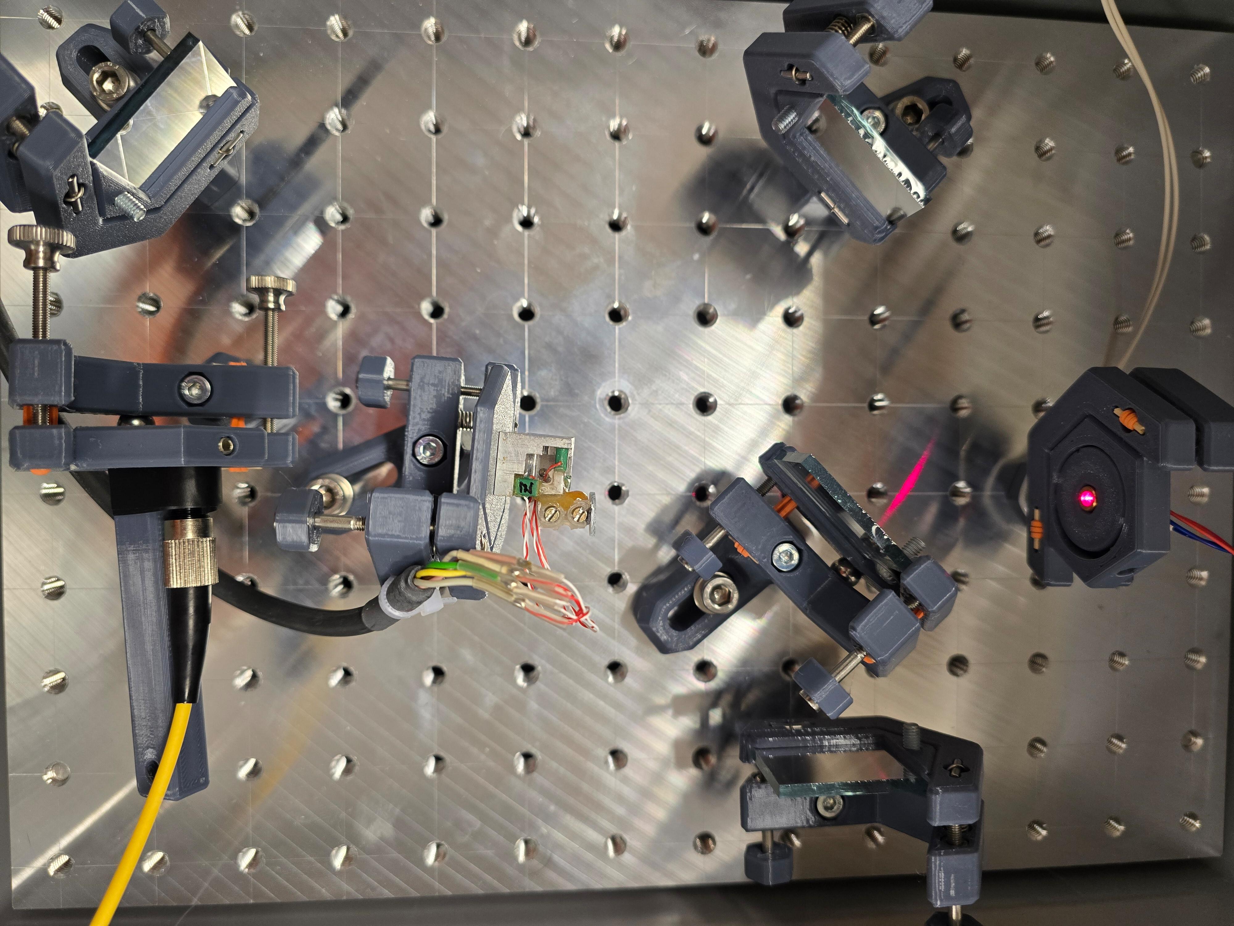
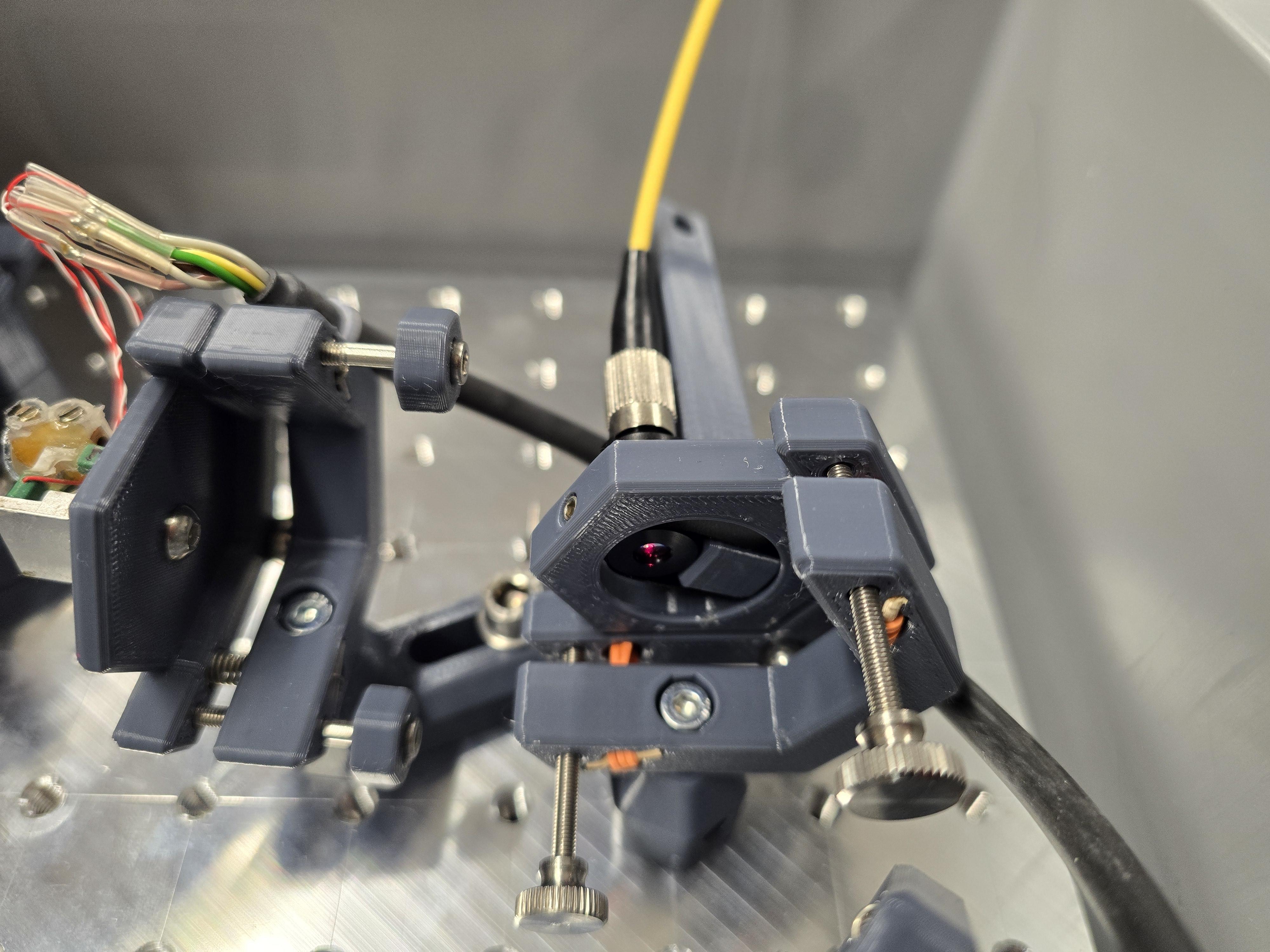
Way forward: We need a proper mount for the fiber collimator, such that we can use a pinhole to pre-align the beam as good as possible for getting a first signal. With unclear exact mounting angle, it will get very difficult to get a first signal. Back tracking the backreflection did not yet lead to success.
Day 2026-01-19 (k8ik, rahix)
Worked a bit towards readout software for the interferometer.
Ordered a cheap fiber + collimator optics in hopes that we can use it to improve our beam profile (see 2025-09-06 notes).
Day 2026-01-18 (k8ik, rahix)
Built up two more mirror mounts and a special mount for the STM head (we want to measure piezo displacement).
Placed the camera into the interferometer to take a look at the interference pattern digitally. Hello world:

A small video recording of the pattern is here: 2026-01-18-170546-interference.mp4 (adjustments were made at some points during the capture)
- The pattern is again very very stable (in our terms, at least…) after tuning the diode “current” (actually the voltage).
- Did record some footage of the pattern idling. you can see room vibrations to some degree. and from time to time the mode seems to jump or get chaotic.
- Assuming we can work with this for first measurements.
Here is the current setup of the interferometer. Optics in a euro container is turning out very nice :)

And here is an annotated version:

- Red arrows are the beam path
- 1: Laser diode
- 2: Beam splitter cube (non-polarizing)
- 3: First leg mirror
- 4: Second leg mirror
- 5: Redirection mirror
- 6: Camera (bare sensor, without any lens)
Started setting up the STM head optics mount:

We glued a tiny (10mm) jewelry mirror to the head. It's not a first surface mirror but we get clean interference patterns anyway. The mirror is not perfectly aligned with the piezo axis. We will have to see if this is going to become a problem.
“Experimented” with innovative cleaning agents: https://social.fa-fo.de/@fafo/115917130152651864
Day 2026-01-11 (k8ik, rahix)
Started setting up a basic michelson interferometer to get a feel for the current system.

No readout yet, but a viewing screen and an F=35mm lens. We can see the fringe pattern and we can even align the beams for almost perfect colinearity so we only see the center dark spot.
Using the cheap laser diode which doesn't allow for proper current control. Played with the voltage to find a stable mode. Somewhere around 3.7V, we found a sweetspot.
Considered readout options: We will most likely try to use the camera in hopes that we can use some tricks to get better resolution with it. The alternative would be a photodiode.
Thinking about using a fiber as a hack to turn our messy beam profile into a proper gaussian.
Day 2025-09-07 (rahix)
Used the laser to characterize the vibration isolation of the STM, see Lab Notes for the STM (2025-09-07).
Results are documented in Laser-Wobble.ipynb from Calculations/ (Rendered Notebook).
Day 2025-09-06 (rahix, q3k, hugo)
Measured beam profile at varying distance, see Lab Notes for the STM (2025-09-06).
Left to right: 50mm, 100mm, 200mm, 400mm. The 400mm measurement includes a mirror which is why the orientation is flipped.


Day 2025-09-05 (rahix)
Played with camera and beam profile readout, see Lab Notes for the STM (2025-09-05)