

meta data for this page
Lab Notes for Optics Experiments
These are the lab notes for our optics experiments. Check the Laser Optics & Interferometry project page for an overview of the project.
This page is a lab notebook. It documents the work done in the lab and our thoughts, theories, and findings related to it. Everything you read here is work in progress and not final results. We believe it is best to have our lab notes out in the open, because it gives more detailed insight into what worked for us and what didn't. Of course you can also use this page to follow our progress!
Day 2026-10-03 (rahix, guest)
More attempts at alignment with the Open Micro-Manipulator. Managed to get quite consistent coupling efficiency again. Working towards automatic alignment optimization.
For this, we pointed the collimated fiber output at the camera-branded camera. After quite a bit of fiddling with the camera, managed to get it to fixed exposure at an acceptable level (Something about using the Auto AWB feature I think??).
Truly an experiment setup:

On the camera, we never see a stable beam, it always looks extremely wobbly:


We placed the fiber output and camera on the vibration-isolated optics breadboard. A bit better, but still significant (pictures above were afterwards). We are very certain the remaining wobbles is vibration in the fiber alignment part, as you can excite it easily by hand. The missing vibration isolation is very noticeable, even floor vibrations have a visible effect. By eye, you cannot see these fast intensity fluctuations in the output intensity.
Built a proxy server for allowing network-access to the motion controller and the measured intensity. See alignment/control-proxy for details.
Started working on a tool to sweep areas around the focus region to automatically improve alignment. In a dry run, we already see the expected intensity profiles along the sweep.
With how things are aligned in the diode case right now, we are always very close to hitting the fiber on the casing/brass rod. This makes alignment in the Z direction quite annoying.
Day 2026-09-27 (anuejn, rahix)
Now using the Open Micro-Manipulator for attempting fiber alignment.

Once the setup is done: Works amazingly well! The speed and large range of motion of the micro-manipulator make the process much faster. So far, best case light output was compareable to the openflexure. But we still lack a good way to quantify it…
Tried setting up a camera with a microscope objective for getting a better look at the fiber end. Unfortunately that didn't work out with the hardware we have in the lab. Switched back to the original setup with the soldering microscope.
The fiber end was re-cleaved for todays alignment. Unfortunately ran out of time before we could do another attempt at glueing the fiber…
Day 2026-09-14 (rahix, guest)
Installed the commercial ND filter in front of the microscope. It does, in fact, not fit the thread. But nothing that some adhesive tape can't fix… With the ND filter, we can dim the picture enough to see some more structure on the fiber end, without overexposing everything.

Managed to use this to quickly get alignment much better and significant light output.
Re-installed the brass rod in preparation for gluing the fiber. We filed down the end of the brass rod because it gets too close to the focus of the laser. So far the rod is not secured with loctite (recommended is loctite 603).
Final alignment using microscope and visual intensity estimate.
First attempt at glueing but we just made a big mess. Also no good coupling with wet glue applied, maybe we dirtied the fiber end… Will try again next time.
Day 2026-09-05 (rahix, guest)
Re-did alignment without vibration isolation but without great results. Started thinking about instrumenting the openflexure with more software to automate large parts of the alignment sweep.
Tried swapping the microscope for a camera with macro-lens but this didn't get us enough magnification. Maybe we can adapt proper microscope optics to a camera instead…
Day 2026-08-29 (leah, rahix)
Investigating whether we can just buy an ND filter for our specific microscope. There is a small cover glass on the front with ø=36mm. Seems to have a M34x0.5 thread? There seem to be some “37mm” ND filters available that seem they could fit.
Mom, we have ND filter at home (2 pieces of polarization filter foil):

But we are still not seeing much improvement.
Removed the brass rod for now as it is just in the way for experimentation.
After lots of trial and error, we achieved some coupling again. But we never got it really good and unfortunately the magnification of our microscope is just not good enough to see the focus spot on the end of the fiber.
Clamped the fiber with a protective sleeve now so we don't damage it again. Sometimes, this leads to the fiber being angled. This is a problem as even a few degrees already lead to much much worse coupling efficiency.
With the light output we got, coupled it into the interferometer setup. We get really nice fringes, though unfortunately hard to take a picture of…

Added some 26cm path length difference to the interferometer to see if we get some amount of coherence length. Result: We do! Fringe contrast has not visibly decreased.
Going back to the topic at hand:
The assembly is probably not stiff enough as it stands to meaningfully perform alignment. We removed the vibration isolation again to get some more stiffness from resting directly on the table surface and this helps quite a bit… Achieved better coupling than in the earlier attempts today. Should probably place the whole assembly onto a breadboard or metal base plate.
Also we need to investigate what we can use to better check focal plane alignment of the fiber end, with the microscope not working out.
Considering to just automate the focus search entirely instead of manual stepping. But backlash of the openflexure is considerable which may make this rather difficult.
Day 2026-08-07 (rahix, guest)
Remounted the microscope to get a better view of the fiber end. It still overexposes which currently makes it impossible to see where the beam waist is. Thinking about strapping an ND filter to the microscope objective…

During realignment, we noticed that our mounting bracket that holds the fiber to the open flexure has crushed the coating of the fiber quite severely. It looks like the core is still intact inside, but maybe we want to figure out a more gentle mount in the future.

[squished fiber under the microscope]
Played a bit with aligning the fiber, bit didn't get too far since we ended up with a very unadvantageous angle of the mounted fiber in relation to the diode casing.
In any case, have some pretty microscope images of the business end of the diode module setup:


[for scale, the brass rod beneath the fiber is ø2mm]
Day 2026-08-01 (rahix, anuejn)
Started setting up the diode module experiment again. Ran into some issues due to not being able to ground the DC supply… Pretty sure we had it grounded last time? But it makes sense, the laser diode will short the supply to VCC in that case. Got it working to the point of setting up the laser diode for 28mA operation.
Also set up the interferometer and produced some tiktok brainrot: https://youtube.com/shorts/R46GZN6YByc
Next step will be improving alignment of the fiber.
Day 2026-07-24 (rahix)
Briefly checked the system again. Alignment didn't degrade since yesterday, output seems qualitatively similar. Assuming either the isolation helped or the current alignment sits further from the beam waist and thus is less sensitive to position change.
Day 2026-07-23 (rahix, guest)
Simplified the vibration isolation by just resting the alu extrusion frame on some small compression springs.
Disassembled the entire diode module again to add slightly more clearance for the lens. We hope this will allow it to be adjusted a bit easier.
Indeed lens alignment got a lot easier with tweezers and the doubled up tape sitting under the lens step. Managed to move the beam waist very very close to the end of the fiber rod (the brass rod that will later hold the fiber). This also means the optics are now a lot more axis aligned.
Took some time to design the case lid with its mounting holes. It now has two M6 through holes spaced √2×25mm apart so it can later be mounted diagonally on an optics breadboard.

Also designed a mount for the microscope, so it is directly attached to the frame of the alignment jig.
Aligned the fiber again a few more times. Backlash in the OpenFlexure is quite noticeable with us moving across the focus spot quite a few times.
Replaced the 15cm fiber with one about a meter long.
Mounted the collimator onto an optics breadboard to send the beam through a michelson interferometer. Didn't have enough time to check stability yet.
Day 2026-07-22 (rahix, guest)
Started building the jig to perform the fiber alignment.

Started getting the sangaboard and openflexure firmware working. We have a pico2 instead of a pico, the patched firmware is available here: https://git.fa-fo.de/q3k/sangaboard-firmware
Install it on the board using platformio:
# If necessary, install udev rules for platformio
curl -fsSL https://raw.githubusercontent.com/platformio/platformio-core/develop/platformio/assets/system/99-platformio-udev.rules | sudo tee /etc/udev/rules.d/99-platformio-udev.rules

# Remove the `upload_port = /media/filip/RPI-RP2` line from `platformio.ini`

# Flash firmware for pico2
pio run -e pico2 -t upload
Ideally, have a RaspberryPi for running the microscope software as documented here: https://openflexure.org/projects/deltastage/install
We don't, so here's the steps to run it directly on your hacker laptop:
git clone https://git.fa-fo.de/rahix/openflexure-microscope-server.git
cd openflexure-microscope-server

# Build the webapp
cd webapp
export NODE_OPTIONS=--openssl-legacy-provider
npm install
npm run build
cd ..

# Prepare the server
pyenv init
pyenv install 3.7.3
pyenv local 3.7.3

python -m venv .venv
source .venv/bin/activate
pip install --upgrade pip wheel pipenv
pipenv install  # May not work, then install deps from setup.py manually

python -m openflexure_microscope.api.app
Once the UI is running, go to http://localhost:5000/#. In the settings, select Delta stage:

Coordinates are marked on the stage:

The Z axis is inverted, so + faces down. You can invert the jog direction in the settings. We current selected a step size of 1000 units per jog.
Installed the diode into the housing. We had to shorten the legs a bit to make the diode socket sit flush in the clamp block on the back.


Set up the driver and drove the diode at 25mA.
Due to unclear design, the ø2mm bearing balls do not fit into the case. Instead of trying to mangle the case, we decided to instead round off the heads of the grub screws using the patented cordless drill as a lathe hack. The fiber rod now sits directly on the two grub screws.

Tried positioning the lens in roughly the right position so the beam waist sits right at the end of the fiber rod. This proved to be extremely tricky… We placed some doubled up capton tape (6-7 layers) under the lens step (the lens outer shape has a .5mm step) to keep it more upright.
Got the lens roughly aligned. Instead of glueing it down directly, we fixed it in place using a 3d-printed holder clamp:

Stripped and cleaved a section of the 635nm SM fiber (about 150mm). Clamped it down on the OpenFlexure Delta stage to align it to the beam waist of the laser. Attached a digital microscope to the whole contraption to see the alignment of the fiber end.


After a bit of searching and also coarse aligning the module to the deltastage with the fiber by hand, we got enough light coupled into the cladding/coating of the fiber to see a faint light at the other end.
Continued alignment using the DeltaStage with 1000 unit jog step size. Managed to get a visible spot on a surface. Since the (other) fiber end was still an unclean cut, we also stripped and cleaved it. Most of the coupled-in light got lost with the stripped back coating. Still a bit of light remaining in the core.
Used this light to further adjust the position of the fiber using the DeltaStage. First with 250 units step size, then 50. With 50, the backlash of the steppers in the stage got quite noticeable.
Installed a temporary testing FC connector (AliExpress) on the end of the fiber. Here's the exiting mode:

Plugged the temporary FC connector into a fiber collimator lens. We get a really pretty beam :)

Placed our camera in front of the collimated beam to profile it and measure intensity. We ran into issues with adjusting the camera exposure again so this didn't really work.
Played a bit more with the alignment, but without significant improvements.


Left the setup for about 30mins. Over time, the coupling efficiency got a lot worse again; assuming thermal drift of the openflexure stage.
Noticed vibration sensitivity of the whole setup, especially in the final camera picture of the beam. Made an attempt to stack the entire thing onto a heavy euro container ontop of an inflated bike tire. Didn't really help too much, we will need a better solution.
Day 2026-07-18 (rahix, guest)
Cases are ready:

Day 2026-07-17 (rahix, guest)
Since we do not have a FAFO laser driver design yet (see techtree #85), we are going to use an LD1100 (Thorlabs) module. We set up the module for the diode and verified everything works:

Selected gain for the LD1100 is max Imon=260µA. The diode monitoring current is specified for 150µA typ., but up to 400µA. With the selected gain and this diode, it works out well and the diode is easily driven at about 30mA.
Wired up the diode socket to a 3-pin dupont header. The wires are labelled with 1, 2, 3 rings for pin 1-3 of the diode. For pin code A diodes like the one we are using, this means:
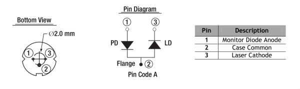
And it lines up with the pinning of the LD1100 so you can connect it directly, as visible in the picture.
In the meantime, somewhere else, we machined the case(s) for the diode modules:

The CAD really doesn't do it justice how small this is!
Day 2026-07-16 (rahix, guest)
We decided to build two versions of the module case. Increasing the distance between lens and fiber end, we can much improve the theoretical coupling efficiency. But this comes at the cost of being much more sensitive to lens alignment (0.1mm shift of the lens moves the focus spot by 1.6mm). So we will need to see if we can pull it off.

[The longer module with more ideal coupling conditions]
With this longer design, the TEM₀₀ beam diameter at the waist is 3.66µm which matches the MFD (mode field diameter) of the selected fiber. With the shorter design, we are at 2.2µm. The rayleigh length (long version) thus is zR = 16.6µm.
On the laser diode side, we capture 23° (half angle) of the emitted light (Compared to 18° with the shorter design).
Day 2026-07-15 (rahix, guest)
Continued working on the diode module design. It lives here: https://git.fa-fo.de/rahix/FiberCoupledLaserModule

Main changes of our assembly against the original design:
- Slightly larger to accommodate larger lens with longer focal distance
- Diode is not press-fit into the housing but rather clamped from the back – we will also use the block clamping the diode to provide thermal control (Using a TEC + NTC)
- Mounting solution for fixing the assembly to an optics breadboard
Short list of selected components:
| Component | Part | Specifications | Link |
|---|---|---|---|
| Laser Diode | L635P5 | 635nm, 5mW, Ø5.6mm | https://www.thorlabs.com/item/L635P5 |
| Diode Socket | S7060R | for Ø5.6mm diodes | https://www.thorlabs.com/item/S7060R |
| Aspheric Lens | CAY046 | Acrylic, Ø7.40mm, f=4.60mm, 0.40 NA | https://www.thorlabs.com/item/CAY046 |
| Single-Mode Fiber | SM600 | 633-780nm, MFD=3.6-5.3µm@633nm | https://www.thorlabs.com/single-mode-fiber?pn=SM600 |
Day 2026-07-12 (rahix, guest)
We want to build a fiber-coupled laser diode module like the one shown by Diffraction Limited on YouTube: Building Fiber Coupled Laser Modules.
Our module will include a few modifications to better suit the metrology applications we have in mind:
- TEC for temperature stabilization
- NTC for temperature stabilization
- A different lens
- Breadboard-mounting option
Our plan is to use an OpenFlexure Delta Stage for performing the fiber alignment.
Day 2026-04-04 (k8ik, rahix, many guests)
We presented our low-cost optics and the interferometer at EH23! Watch our talk here: Budget Beams – Laser Experiments in a Hacker Lab

During the event, our laser diode broke (well, rahix fed it too much voltage really) so we scrambled to disassemble a DVD drive and extract the red 650nm diode from it. We kept the collimation optics from the DVD drive and hot-glued the entire subassembly to an optics mount. It took 3 attempts (3 DVD drives) to not immediately kill the new diode again.
We managed to demonstrate the fringe movement from the piezo quite a few times. We borrowed a different power supply to drive it. This one seems to lead to a slow ramp-up of voltage (fringes move slowly when turning on) and an abrupt cutoff (fringes fall back very quickly when turing off).
Stability was quite alright with the reduced isolation setup as long as nobody touched the table.
Day 2026-04-01 (k8ik, rahix)
Set up the interferometer experiment again, but with “analog” readout (i.e. just a viewing screen where the pattern is enlarged).
Tried driving the Z-axis piezo of the STM head with +20V. We can see movement! When turning on the voltage, the pattern immediately jumps. When turning it back off, it slowly drifts back to its original state.
Eyeballed the movement to be somewhere below λ/2, so <300nm. But for any proper measurement, we need to do digital readout again.
Getting the laser stable enough to see the movement without noise is not easy. The mechanics hold up plenty fine.
Day 2026-02-21 (k8ik, rahix)
We successfully coupled our shitty Aliexpress laser into the also high quality single mode fiber. However, we do see a beautiful beam but also what could be higher modes in the output, meaning the fiber is either broken at the end, the collimator has some issues or the fiber is indeed a multimode fiber. Most likely explanation right now: The fiber is a “broadband single mode fiber” for infrared (not specified) meaning it could allow for higher modes at 650nm.


We put a collimator on the other fiber end and aimed it at our camera to take some beam pictures.
Wrote a little script which outputs the average intensity across the camera frame as a single number so we can tune the fiber coupling against it live_intensity.py.
Even after adjustment, only very little power coming out of the fiber. After tuning, we readjusted the exposure of the camera to try imaging full beam pictures (but this only partially worked because the auto exposure setting of the camera is completely broken).
First, here is a capture of a higher mode:

With a bit more tuning of the fiber coupling, we end up seeing some much nicer beam shapes:


The curve does not look gaussian which is a bit worrying. Current assumption is that this is still a higher transversal mode that just looks close enough.
Day 2026-01-31 (k8ik)
Aliexpress quality fiber and collimators arrived:
Fiber:
Fiber Link
Aliexpress description: SC To SC LC ST FC To FC Fiber Patch Cord Jumper Cable SM Simplex Single Mode Optic Drop FTTH Cable For Network 1m
Collimators:
Collimators Link
Aliexpress description: Collimator Aspherical fiber focusing light spot adjustable size FC interface
Rebuild our setup (removed the cube) to test the fiber. The fiber will enable us to get a nice Gaussian beam profile with which we can work in the future. Built in the fiber in a very adventurous setup because we do not yet have a mount printed. Tried to couple in the laser but did not succeed yet. The fiber is built very close to the first mirror and quite far to the second to decouple place and angle of the beam entering the fiber. As detector tried the bare eye (without collimating optics at the fiber end). Need complete darkness to get first signal to optimize on next time.


Way forward: We need a proper mount for the fiber collimator, such that we can use a pinhole to pre-align the beam as good as possible for getting a first signal. With unclear exact mounting angle, it will get very difficult to get a first signal. Back tracking the backreflection did not yet lead to success.
Day 2026-01-19 (k8ik, rahix)
Worked a bit towards readout software for the interferometer.
Ordered a cheap fiber + collimator optics in hopes that we can use it to improve our beam profile (see 2025-09-06 notes).
Day 2026-01-18 (k8ik, rahix)
Built up two more mirror mounts and a special mount for the STM head (we want to measure piezo displacement).
Placed the camera into the interferometer to take a look at the interference pattern digitally. Hello world:

A small video recording of the pattern is here: 2026-01-18-170546-interference.mp4 (adjustments were made at some points during the capture)
- The pattern is again very very stable (in our terms, at least…) after tuning the diode “current” (actually the voltage).
- Did record some footage of the pattern idling. you can see room vibrations to some degree. and from time to time the mode seems to jump or get chaotic.
- Assuming we can work with this for first measurements.
Here is the current setup of the interferometer. Optics in a euro container is turning out very nice :)

And here is an annotated version:

- Red arrows are the beam path
- 1: Laser diode
- 2: Beam splitter cube (non-polarizing)
- 3: First leg mirror
- 4: Second leg mirror
- 5: Redirection mirror
- 6: Camera (bare sensor, without any lens)
Started setting up the STM head optics mount:

We glued a tiny (10mm) jewelry mirror to the head. It's not a first surface mirror but we get clean interference patterns anyway. The mirror is not perfectly aligned with the piezo axis. We will have to see if this is going to become a problem.
“Experimented” with innovative cleaning agents: https://social.fa-fo.de/@fafo/115917130152651864
Day 2026-01-11 (k8ik, rahix)
Started setting up a basic michelson interferometer to get a feel for the current system.

No readout yet, but a viewing screen and an F=35mm lens. We can see the fringe pattern and we can even align the beams for almost perfect colinearity so we only see the center dark spot.
Using the cheap laser diode which doesn't allow for proper current control. Played with the voltage to find a stable mode. Somewhere around 3.7V, we found a sweetspot.
Considered readout options: We will most likely try to use the camera in hopes that we can use some tricks to get better resolution with it. The alternative would be a photodiode.
Thinking about using a fiber as a hack to turn our messy beam profile into a proper gaussian.
Day 2025-09-07 (rahix)
Used the laser to characterize the vibration isolation of the STM, see Lab Notes for the STM (2025-09-07).
Results are documented in Laser-Wobble.ipynb from Calculations/ (Rendered Notebook).
Day 2025-09-06 (rahix, q3k, hugo)
Measured beam profile at varying distance, see Lab Notes for the STM (2025-09-06).
Left to right: 50mm, 100mm, 200mm, 400mm. The 400mm measurement includes a mirror which is why the orientation is flipped.


Day 2025-09-05 (rahix)
Played with camera and beam profile readout, see Lab Notes for the STM (2025-09-05)